
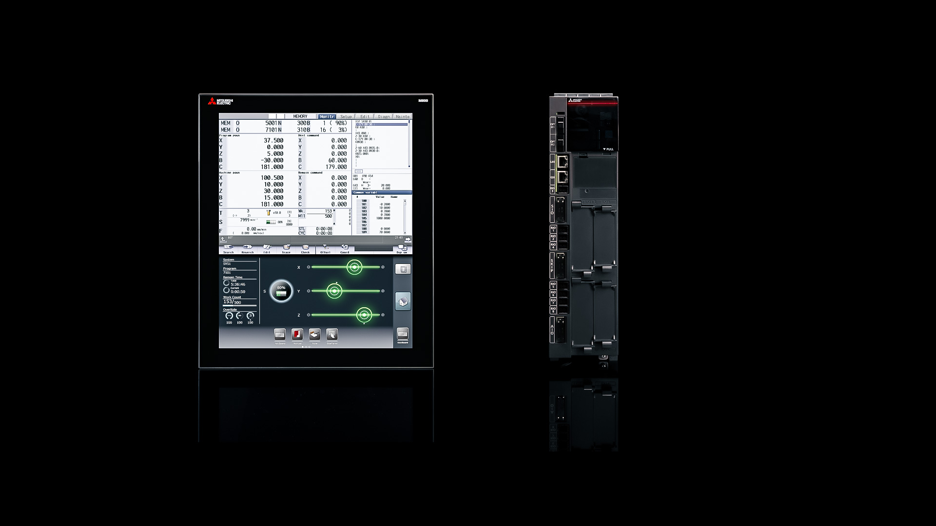
High productivity, usability and flexibility delivered by breakthrough performance. The next-generation CNC M800/M80 Series empowers the manufacturing industry with unlimited possibilities and the capability to create innovative value.
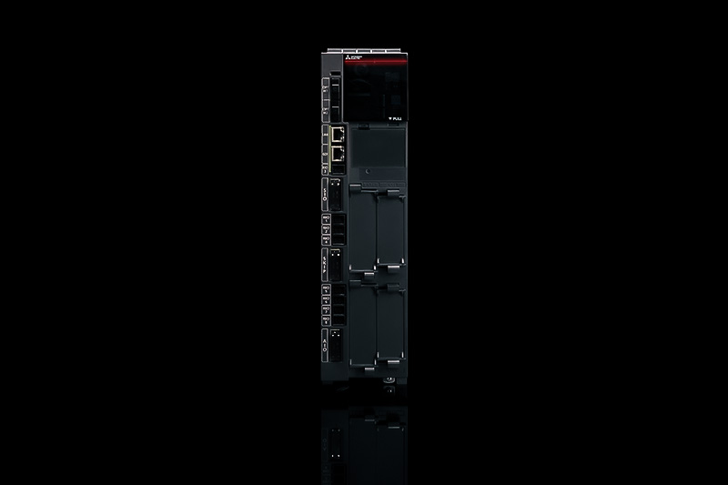
Incorporating the CNC-dedicated CPU in the new series not only results in phenomenal processing speed, but also reduces the number of required parts, leading to fewer possibilities of failure and increasing product quality. Equipped with Mitsubishi Electric’s first-ever CNC-dedicated CPU, the long-awaited M800/M80 Series is the fruit of an original development process and the sum of our latest technologies. With the utmost confidence, we are proud to introduce the M800/M80 Series and invite customers to experience performance of the future today.

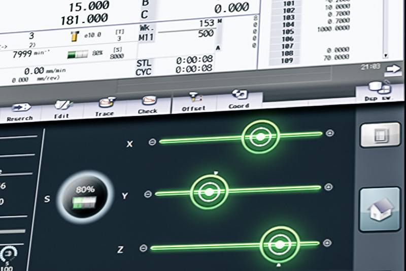



The CNC provides new tool management screen, where you can gather and manage tool-related information with greater convenience. A wide range of setting items such as tool name and tool ID are readily available. You can read or write tool data or add custom data via ladder or machining program.
M800/M80 Series offers SSS 4th-generation (SSS-4G) control, enabling high-speed, high-accuracy, high-quality machining. SSS-4G control provides features that are effective in reducing tact time, including optimal acceleration/deceleration suited to each axis’ characteristics. In addition, SSS-4G is capable of reducing machine vibration during high-speed cutting. SSS-4G control allows for greater cutting accuracy in the same length of time, or shorter cutting time with the same degree of accuracy when compared to our previous models.
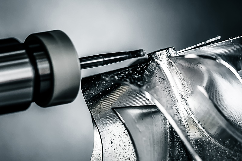
High-speed high-accuracy control features accumulated originally for machining centers are now available in lathe system. Fine milling can be implemented at high speeds on a lathe. This CNC enables a servo motor, instead of a spindle, to act as a tool spindle. Any of the servo control axes driven by multi-hybrid drive can be used as a tool spindle. This contributes to the downsizing of machine tools.
CNC-dedicated CPU is incorporated in the M800/M80 Series, providing significantly improved short segment processing capability. The benefits are not limited to improvements in basic performance alone. The Tolerance Control function enables operators to achieve high-quality surfaces simply by specifying the desired dimensional accuracy. This feature takes machining to a whole new level.
M800/M80 Series provides new features that can maximize the full potential of machine tools, including: Variable-acceleration pre-interpolation acceleration/deceleration provides optimized acceleration, with each axis’ characteristics fully exercised. For example, allowing a linear axis to accelerate irrespective of rotary axis responsiveness. “OMR-FF control” allows for optimal position loop gain adjustment suited to each axis, leading to smoother and more accurate cutting. Other than the above, this CNC has new functionality effective for higher productivity, including “Rapid traverse block override function” that helps reduce non-cutting time by overlapping feed blocks.
M800/M80 Series provides “Spindle superimposition control, “a feature that enables simultaneous execution of turni ng and center tapping, although they need to be executed individually. These features are effective in eliminating idle time, resulting in a significant reduction in tact time. This CNC also offers features that maintain synchronization between part systems, which is required for automatic lathes, in particular. These enable operators to implement even more complex machining safely and securely.
This function estimates the work inertia and changes the speed control gain or time constant automatically according to the estimation results to suppress mechanical vibration.
Operators can set machining cycles easily in an interactive manner while monitoring the finished work shape. In addition to the input of normal shape data, you can also extract drawing elements from CAD data in DXF format, and set them as shape data, which makes programming easier. Programmed shape can be checked in 3D graphic check before machining to check for any program error.
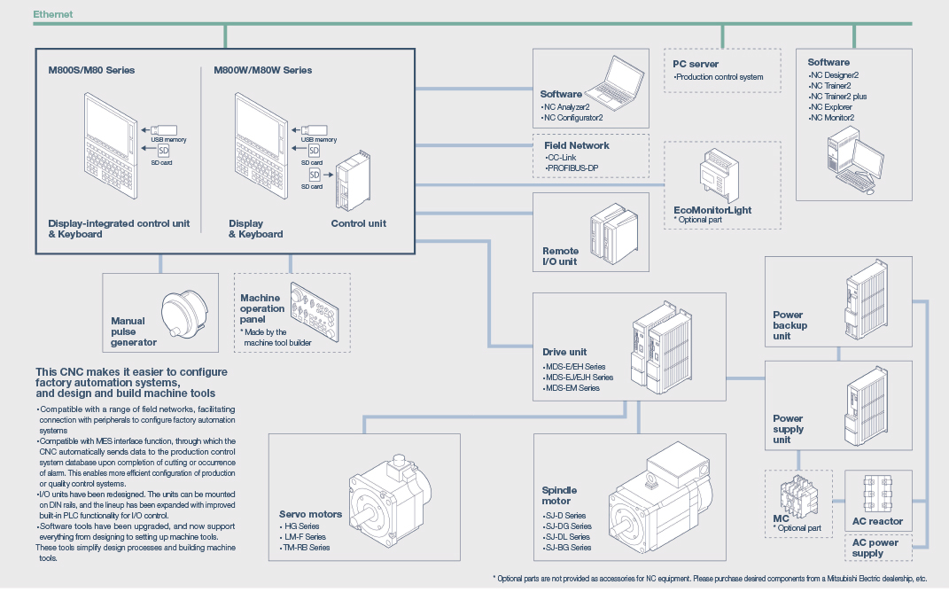
A wide selection of fieldbus networks supports the integration of in factory automation systems. Compatible MES interface function that allows the automatic transmission of from CNC data, such as quantities or maintenance-relevant data to a production control system. This supports the efficient integration into production or Quality control systems.
The I/O modules were newly developed. The modules can DIN rails and have been designed for improved I/O control extended by built-in PLC functionality. Software tools at the highest level support you in the design process to the commissioning of machine tools. Simplify your design and machine manufacturing processes.
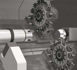
Milling features and multi-axis, multi-part system control features have been significantly improved. Progress has been made in operability, enabling operators to implement ever more complex machining in an easy and efficient manner.


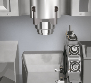
SSS control has further evolved, realizing high-speed, high-accuracy, high-quality machining. In addition, this CNC offers features that bring out the full potential of each axis and minimize non-cutting time, leading to higher productivity


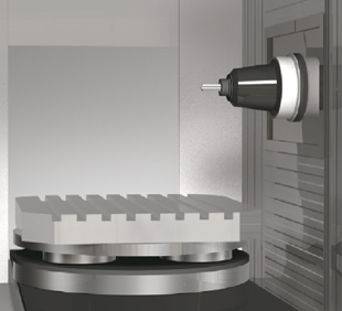
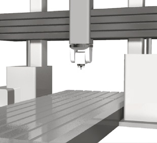
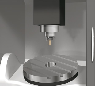
M800/M80 Series provides a range of safety features collectively called the Smart Safety Observation Function. This function has achieved full conformity with the safety standards that cover the entire system including CNC, drive, I/O, sensors and communication.

The data collected from MTConnect compatible device can be imported into Edgecross and used for edge applications etc. MTConnect is an open protocol for machine tools. By using the MTConnect Adapter which is compatible with MITSUBISHI CNC M800 / M80 Series and M700/M70 Series, you can easily collect and utilize various data of the machine tool which works with MITSUBISHI CNC.
To build the “Operation monitoring system”, install NC Visualizer, an operation monitoring application, to your server PC. NC Visualizer displays the machine tool’s status such as “operating”, “stopped”, “alarm”, and “power OFF” in a list, which helps operators to improve the productivity or to analyze the cause of alarms. In addition, the operators can monitor the operating status with an external PC/tablet PC via a Web browser.
The NC screens can be displayed on an external PC/tablet PC. Operator can monitor the machine tool’s status and operate the NC screen without going to the factory floor, which helps to improve the operation efficiency. (The function is enabled on a non-Windows-based NC display. No external computer is required.)
Supports increasing automation needs. Automation can be realized more easily by simple connection and control of the peripheral devices.
I/O units have been redesigned. The renewed I/O communication method makes it possible to significantly increase the maximum number of contact points per channel, enabling a number of peripheral equipment and devices to be controlled by CNC alone.
Built-in PLC functionality for I/O control has been improved. This CNC supports Multi-project PLC, a feature that enables ladder logics for peripheral equipment to be managed separately from those for machine tools. This creates a more efficient environment for operators working together in developing and managing ladder logics.
M800/M80 Series has a feature called Machine Group-based Alarm Stop, which stops operation of individual machine groups if an alarm occurs when control is combined with the MDS-E/EM/EJ Series. This feature allows continuation of machining even when an alarm occurs on a loader, magazine or other peripheral equipment.
| M800VW Series | M80VW Series | ||
|---|---|---|---|
| M850VW | M830VW | M80VW | |
| Max. number of axes (NC axes + Spindles + PLC axes) | ◯16 △32 | ◯16 △32 | 13 |
| Max. number of NC axes (in total for all part systems) | ◯16 △32 | ◯16 △32 | 10 |
| Max. number of spindles | 8 | 8 | 6 |
| Max. number of PLC axes | 8 | 8 | 6 |
| Number of simultaneous contouring control axes | 8 | 4 | 4 |
| Max. number of NC axes in a part system | ◯8 △12 | ◯8 △12 | 8 |
| Max. number of part systems (main+sub) | ◯4 △8 | ◯4 △8 | 4 |
| Max. number of main part systems | ◯4 △8 | ◯4 △8 | ◯2 |
| Max. number of sub part systems | ◯4 △8 | ◯4 △8 | ◯2 |
| Control unit-side High-speed program server mode | △ | △ | ◯ |
| Display unit-side High-speed program server mode | △ | △ | ◯ |
| Least command increment | ◯ 0,1 µm △ 1 nm | ◯ 0,1 µm △ 1 nm | 0,1 µm |
| Least control increment | 1 nm | 1 nm | 1 nm |
| Max. number of tool offset sets | ◯ 128 sets △ 999 sets | ◯ 128 sets △ 999 sets | 256 sets |
| Built-in PLC capacity | ◯ 128000 △ 512000 | ◯ 128000 △ 512000 | 64000 |
| Multi-project [number of projects stored] | ◯ 2 △ 6 | ◯ 2 △ 6 | ◯ 3 |
| Data protection by user's level | △ | △ | ◯ |
| Workpiece coordinate system shift | ◯ | ◯ | ◯ |
| 3D solid program check | ◯ | ◯ | ◯ |
| Interactive cycle insertion | △ | △ | ◯ |
| Multiple spindle synchronization set control | ◯ | ◯ | ◯ |
| Spindle superimposition control | △ | △ | ◯ |
| High-accuracy control | △ | △ | ◯ |
| High-speed high-accuracy control II (G05P10000) max.[kBPM] | △ 168 | △ 168 | ◯ 33,7 |
| SSS control | △ | △ | ◯ |
| Tolerance control | △ | △ | ◯ |
| OMR-FF | △ | △ | ◯ |
| OMR-CC (Optimum Machine Response - Contour Control) | △ | △ | ◯ |
| Rapid traverse block overlap | △ | △ | ◯ |
| Spindle-mode servo motor control | △ | △ | ◯ |
| Real-time tuning 1 (speed gain) | △ | △ | ◯ |
| Real-time tuning 2 (rapid traverse time constant) | △ | △ | ◯ |
| Inclined surface machining command | △ | △ | ◯ |
| 3-dimensional manual feed | △ | △ | ◯ |
| Finish shape view programming | △ | △ | ◯ |
| CC-Link (Master/Local) | □ | □ | □ |
| PROFIBUS-DP (Master) | □ | □ | □ |
| CC-Link IE Field (Master/Local) | □ | □ | □ |
| EtherNet/IP | □ | □ | □ |
| MES interface library | △ | △ | ◯ |
| Machine group-based alarm stop | △ | △ | ◯ |
Refer to the specifications manuals for details. (*1) G/B:Guide Bush (*2) The 8.4-type display unit is incompatible. (*3) Windows-based display unit/Windows-less display unit (*4) Limited to the simultaneous 4-axis contouring control.
| M800VW Series | M80VW Series | ||
|---|---|---|---|
| M850VW | M830VW | M80VW | |
| Max. number of axes (NC axes + Spindles + PLC axes) | ◯ 16 △ 32 | ◯ 16 △ 32 | 11 |
| Max. number of NC axes (in total for all part systems) | ◯ 16 | ◯ 16 | 9 |
| Max. number of spindles | 6 | 6 | 4 |
| Max. number of PLC axes | 8 | 8 | 6 |
| Number of simultaneous contouring control axes | 8 | 4 | 4 |
| Max. number of NC axes in a part system | ◯ 8 △ 12 | ◯ 8 △ 12 | 8 |
| Max. number of part systems (main+sub) | ◯ 2 | ◯ 2 | ◯ 2 |
| Max. number of main part systems | ◯ 2 | ◯ 2 | ◯ 2 |
| Max. number of sub part systems | ◯ 2 | ◯ 2 | – |
| Control unit-side High-speed program server mode | △ | △ | ◯ |
| Display unit-side High-speed program server mode | △ | △ | ◯ |
| Least command increment | ◯ 0,1 µm △ 1 nm | ◯ 0,1 µm △ 1 nm | 0,1 µm |
| Least control increment | 1 nm | 1 nm | 1 nm |
| Max. number of tool offset sets | ◯ 200 sets △ 999 sets | ◯ 200 sets △ 999 sets | 400 sets |
| Built-in PLC capacity | ◯ 128000 △ 512000 | ◯ 128000 △ 512000 | 64000 |
| Multi-project [number of projects stored] | ◯ 2 △ 6 | ◯ 2 △ 6 | ◯ 3 |
| Data protection by user's level | △ | △ | ◯ |
| 3D solid program check | ◯ | ◯ | ◯ |
| Interactive cycle insertion | △ | △ | ◯ |
| Spindle superimposition control | – | – | – |
| High-accuracy control | △ | △ | ◯ |
| High-speed high-accuracy control II (G05P10000) max.[kBPM] | △ 168 | △ 168 | ◯ 101 |
| High-speed high-accuracy control III (G05P20000) max. [kBPM] | △ 540 | △ 540 | ◯ 202 |
| SSS control | △ | △ | ◯ |
| Tolerance control | △ | △ | ◯ |
| Variable-acceleration pre-interpolation acceleration/deceleration | △ | △ | – |
| OMR-FF | △ | △ | ◯ |
| OMR-CC | △ | △ | ◯ |
| Rapid traverse block overlap | △ | △ | ◯ |
| Spindle-mode servo motor control | △ | △ | ◯ |
| Real-time tuning 1 (speed gain) | △ | △ | ◯ |
| Real-time tuning 2 (rapid traverse time constant) | △ | △ | ◯ |
| Tool center point control | △ | △(*2) | ◯(*2) |
| Inclined surface machining command | △ | △ | ◯ |
| 3-dimensional manual feed | △ | △ | ◯ |
| Finish shape view programming | △ | △ | ◯ |
| CC-Link (Master/Local) | □ | □ | □ |
| PROFIBUS-DP (Master) | □ | □ | □ |
| CC-Link IE Field (Master/Local) | □ | □ | □ |
| EtherNet/IP | □ | □ | □ |
| MES interface library | △ | △ | ◯ |
| Machine group-based alarm stop | △ | △ | ◯ |
Refer to the specifications manuals for details. (*1) G/B:Guide Bush (*2) The 8.4-type display unit is incompatible. (*3) Windows-based display unit/Windows-less display unit (*4) Limited to the simultaneous 4-axis contouring control.
This manual describes the specifications of Mitsubishi Electric CNC.
This manual describes the specifications of Mitsubishi Electric CNC.
This manual describes the various signal interfaces and functions of the NC unit required when creating Mitsubishi Electric CNC sequence programs (built-in PLC).
Manuals related to M800/M80/E80/C80 Series are listed as follows.
This manual covers the items required for maintaining the MITSUBISHI CNC M800/M80/E80 Series.
This manual describes how to carry out MITSUBISHI CNC programming.
This manual describes how to carry out Mitsubishi Electric CNC programming.
This manual is a guide for using the MITSUBISHI CNC M800/M80/E80 Series.
This manual explains the PLC development environment.
This manual covers the items required for installing, connecting and setting up the MITSUBISHI CNC.
This manual covers the items required for installing, connecting and setting up the MITSUBISHI CNC.
M800-M80-E80-C80 Series HAND BOOK
This manual is a guide for using the MITSUBISHI CNC.
Fields marked with a * are mandatory.
Mitsubishi Electric Europe B.V.
German Branch.
Mitsubishi-Electric-Platz 1
D - 40882 Ratingen
Tel.: +49 (0)2102 / 486 - 0
Fax: +49 (0)2102 / 486 - 1120
cnc.sales@meg.mee.com

Benjamin Buzga
CNC Sales & Business Development Manager